Friday, November 20, 2015

Lasercut MDF speaker enclosures

A fellow lab mate has been working on neat digital musical instrument design tools and making extensive use of a lasercutter for building prototypes. One thing I decided to try was using similar materials and techniques to quickly make speaker enclosures. I had a few HiVi B3S lying around, and have always wanted to make this design from zaph audio as a simple but good quality sounding kit. (confession: I totally skimped out on the crossover part). My attempt previously had worked, and while the little HiVi drivers gave out quite good sound, I can't help but the enclosures were holding the system back ;). So, armed with a relatively hassle way of quickly making very precise volume boxes together, I cobbled up a design using the handy makerbox.io tool and Inkscape. The former allows you generate finger joint designs of a specific dimension given a number of input parameters (the most important being the thickness of your material). Then I went into Inksscape and carved out the mounting holes and driver cutouts.

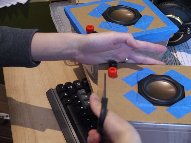
The project took two major iterations. First was making a perfectly sized box (according to zaph's design) with the driver and mounting cutouts, and then adjusting it due to issues encountered by the limitations of the materials used (i.e. very thin MDF).

P1050201
Old buildhack, showing the plastic box+cardboard baffle of the previous version and version 1 of the new design with single layer baffle


There were two main challenges I had with the new design, both relating to the baffle, or front surface where the driver is mounted:

1.) Because the 1/8" MDF is relatively thin, the baffle will actually bow forward a bit when the driver is mounted

2.) The finger joints are great at making an enclosed box, but once glued it is impossible to open it again without destroying the box. I didn't have the heart to simply glue everything together, and it's generally good to have your internal components accessible. Therefore, I had to come up with a removable baffle solution.

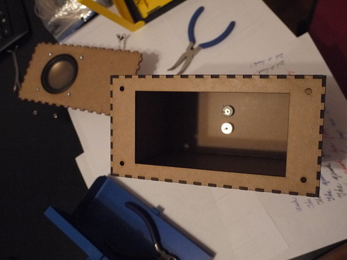
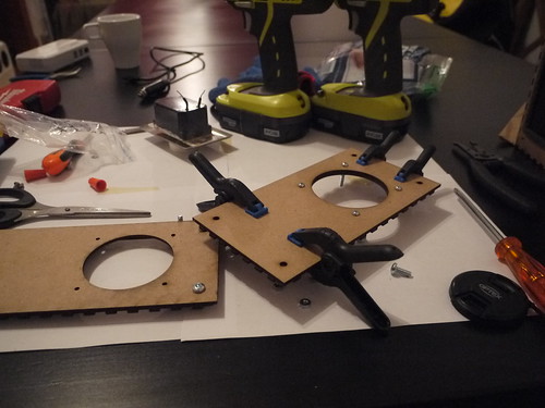
So, in the second iteration, I decided to double up on the front baffle (by simply gluing two pieces on top of each other), and then adding a non-removable component with a large hole like this:

P1050246

Then, I put some t-nuts underneath the holes, and lined some insulation foam (weatherstripping) for better seal:


P1050251

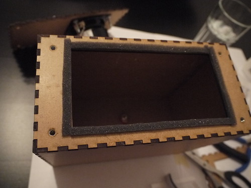
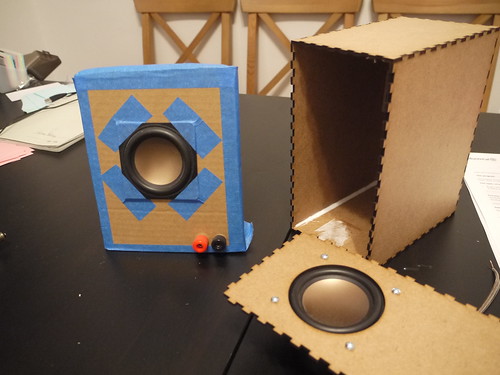
The t-nuts weren't ideal given the thickness of the panels, but with some glue and coaxing it worked. In the end, this design allowed the front baffle with the driver mounted to be screwed in. Here shows the version 1 (left) and version 2 (right) of the enclosure:

P1050259
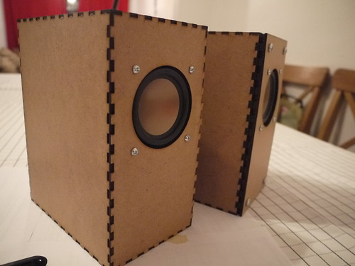
Version 1 (left) shows a press-fit of the finger joint, and if I was building a one-off system simply gluing it would have worked but it would be a one-way trip!

The final version adds a bit of extra depth to the front, but allows the baffle to be removed for servicing. There is a slight gap since I recycled the old front baffle piece that had the finger joint edges. If I was to make a new version, I would simply cut out two non-jointed pieces (or even better: use thicker MDF if the cutter allows!). Below you can see the straight-cut piece with the old jointed piece glued underneath:

P1050257

All in all, it was a pretty fun project and good introduction to lasercutting. In terms of the sound while it is significantly improved over the plastic lunchbox design from before, I think it's still quite a bit aways from Zaph's original: no stuffing, box walls possibly too thin, weather stripping is most likely not as airtight as "speaker-grade" seals, and, perhaps most importantly - no crossover to block out the lower frequencies that the drivers would struggle to output anyway). However, powered by a lepai 2020a+ with signal fed by a small bluetooth adapter dongle, it makes a great kitchen/casual listening speaker with sound quality significantly better than off-the-shelf systems at much higher prices.

Here's a PDF of the lasercut outlines (for a real cut you may want to edit the line thickness to 0.1mm, change the colour etc to settings that your lasercutter requires). The design was done on 3 sheets of 30cm x 60cm 1/8" MDF that you can buy from Home Depot for a few bucks. (Thanks again Filipe for the materials+advice!) You'll need to make your own rear exit holes for the connector mounts of your choice: easiest is to just make two holes for banana plugs, which is what I did.

Could I have done this by hand? Sure. It would be a good practice of woodworking skills, and much easier to use thicker materials. However, there are certain things a lasercutter can do very well and for clumsy/lazy people like myself, this was a good excuse to play around and experiment.

Finally, a plug to Central Stamp for the accessible and quick turnaround laser cutting service!

Monday, February 23, 2015

What do you do when you get your 3D printer back online again? Use it to play music of course!
(and spend hours tweaking until a cube actually comes out as a cube...). A MIDI-gcode converter is responsible for converting MIDI notes into frequencies which are mapped to motor PWM signals. Kinda like the more impressive floppy drive organ

Overall I was surprised at how well it kept over time - I had some concerns over the wood warping. However, there were the typical calibration and bed leveling issues that make me wish I had invested in something with a metal chassis made of aluminum extrusions... Oh well, hope the Rhino 3d printer works out! 


Friday, January 30, 2015

Shutting down the RPi gracefully

One of the things thats worth considering when using an embedded linux system, is the integrity of the file system when it comes to pulling the plug. In the past, I've had issues (especially with poor quality SD cards) with file corruption. The RPi should not be simply disconnected from power when you're done, and if you're running an application without console access (either direct or via ssh), its a good idea to implement the means to shut down the system gracefully.

There is a large number of documentation on how this can be done via a physical switch connected to the GPIO pins. For my implementation, I aimed for the following:

- as few components as possible

- as straight forward header connections as possible

To achieve this, I ended up using pin 05 (GPIO03), which is conveniently located next to a GND (pin 6):


This pin has internal pull-up resistors enabled by default, which means you can use an active-low switch without having to add a resistor. To hook this up simply requires a 1x2 header connection attached to a switch (or bare wires, if you're into that sort of thing) on the other side.

Then, I employed the interrupt method (because polling constantly sucks, right? :P) as described here. The interrupt needs to be modified to trigger on the falling edge instead of rising, due to the active-low logic we're dealing with.

The unintentional bonus of using these two pins is that once the Pi is in the halted state, triggering this pin again will boot it up again! (This is likely a built-in feature which I luckily stumbled upon...)

The one weird thing I discovered, was that the interrupts do not fire when the script is running in the background, which might not be suitable for some usage scenarios since it requires load the python script last and keeping it in the foreground. I'm still investigating this...

Saturday, January 17, 2015

Raspberry Pi, openFrameworks, Analog to Digital stuff

Raspberry Pi, openFrameworks

I've been doing some work with the Raspberry Pi lately with openFrameworks, and it has served as a great reminder how accessible these hardware and software platforms are for building stuff.

Setting up the RPi for oF is super simple, and relatively well documented. The extra hurdle that is worth jumping over in the setup process, is cross compilation. I followed the official guide here, and found a few steps that were missing. The cool thing with oF is that its a very active community, and I was able to update the documentation, and push it to the official webpage within a matter of hours. Currently the instructions should be up to date for the active version (0.8.4).

Cross compiling on a desktop (i7-4770k) VM running Ubuntu sped up the compile time from over 1 hr for the entire library to less than 1 minute. Basic apps went from 2-3 minutes to a couple of seconds. Therefore, the amount of time it takes to set up the cross compile is more than worth it for any kind of significant dev work. Currently my setup involves SCP'ing the compiled binary to the RPi, but it would be possible to set up the shared file system to avoid this step. DistCC is also another way but is slightly more involved (IMO).

Media Performance

One of the applications I'm currently working on for the RPi, is the interactive playback of videos. Due to the well optimized GPU libraries available, the RPi has quite impressive video decoding capabilities for the amount of overall raw processing power. For oF, there is a nice wrapper of the OMXplayer on the Pi which takes full advantage of the hardware decoding capabilities. As such it is possible to easily run HD video in an interactive application in your openFrameworks app. Here's a nice page from creativecoding.net describing a few things you can do to get started with oF and Rpi

Analog to Digital on the RPi

One thing that the RPi lacks, compared to other boards like the BeagleBone Black, is built in analog to digital (A2D). The 26 GPIO pins (or 40 on the newer A+/B+ models) are digital only, so if you want to interface analog sensors, you have the following options:

- Use another microcontroller (such as the Arduino, teensy, etc) on the USB port and run an app that talks to the virtual serial-USB. This is quite common since the set up is very similar to when using such a microcontroller with a desktop/laptop environment. However, it does add a greater cost, and also on systems like the A/A+ board, you only have a single USB port that you might want to use for something else without having to add an extra hub...

- Interface an A2D on the GPIO. There are a few common methods, and each one requires some hardware that provides either: UART, I2C, SPI, or cook you own A2D solution such as described in this excellent post by Hertaville that also demonstrates how typical A2Ds work. For my initial attempt, I used the MCP3008 SPI chip, due to local retailer availability and some quick online reading. To get the pins of the RPi easily exposed on a breadboard, I used the ElecFreaks GPIO adapter kit. I'm not sure if I'm using it correctly, but there seems to be a major flaw in the design of this adapter board: the power rail pins do not line up with the rest of the header pins. Either I'm not using it the right way, or there was a bit of a design flaw here...


Anyway, here's a quick screenshot of a quick test program using using the wiringPi library:


Next steps: brushing up my PCB design to build a small breakout board for this chip, as well as looking at potential alternatives. The drawback of this SPI implementation is that without any further multiplexing, we're limited to one of two channels, which means a max of 16 input pins using 2 MCP3008's.

Sunday, January 04, 2015

DIY cheap-fancy speakers

Swan HiVi 3 inch "full range" speaker drivers (somewhat fancy), housed in the most budget enclosure. Consider using them in stand-alone digital musical instruments, although their weight was surprising. Also sounded quite anemic with a small 5W amp... may need something beefier, which drives up the power budget for portable applications. Right now we're testing these alongside the Pyle 4" cubes, which are amazing little boxes for their price. I suspect a better enclosure, and a low frequency cut-off will make these Swans sound even better...

P1040134

Tuesday, June 17, 2014

Air Organ

I was fortunate enough to have access to a MIDI enabled Casavant organ at our church. The organ is a fascinating instrument in many ways, but one particular is the fact that it was the first instrument where you can change the mapping between the input and output on the fly, and that is an otherwise exclusive feature of new digital musical instruments.

With the ever-improving Leap Motion SDK, and some work related motivation to "yarpify" things, I got the following running after struggling with some typos in my SYSEX messages that are used to control the organ.


The above shows one simple mapping: X (left right) controls the pitch, and moving the hand forward goes from no sound, to a single stop, to a second stop that's making notes a third higher. What was immediately interesting was that the digital control of the organ is extremely fast, and glissing through in this manner created runs that are basically impossible to do on a standard keyboard (well, maybe if you practiced some two-hand technique where you can time the black notes in between the white ones...). Also, it was very apparent that a simple linear X-position to pitch is highly unnatural when you don't have the tangible feedback of a physical, rectangular keyboard.

Friday, May 31, 2013

PENny, a low cost pressure sensitive stylus

PENny is a cheap pressure sensitive addition for a capacitive touch screen. Using the built in audio input and output and an extremely simple passive resistive network, an extra degree of expressivity can be added. Here we see Nicolas testing it out before flying to Korea for NIME2013. Full paper here.

Wednesday, May 01, 2013

Third Places Workshop@CHI2013, Paris

Coffee shops, Paris, and mobile phone choirs - we're very excited to present at the HCI-3P workshop for CHI2013 on bringing music-making to "Third Places" using technology (Extended abstract here). Part of the workshop activities include visiting typical 3rd places (restaurants, bistros, cafes) around Paris.


Somewhat related: here's a visit to Chopin's grave at Père Lachaise Cemetery during one of the afternoons I sneaked off from the conference :)

Monday, August 27, 2012

Vox Tactum is in Europe!

Vox Tactum is touring Europe! We're putting together an interactive art installation based around ChoirMob/(new)Vuzik in the City of Mons in Belgium for the City Sonic festival. The installation runs from Aug 31 to Sep 16. Check out the webpage for more details!

In mid Sep we'll be at ICMC 2012 performing Aura's latest piece for ChoirMob and and Vuzik. In late Sep in Corfu, Greece, for Audio Mostly where we'll be performing Intertwine:


Wednesday, October 05, 2011

Tippy for ICEC 2011

What is Tippy?

Tippy:
- is a Telepresence Robot
- has a simple microcontroller-based drive system
- runs on ANY mobile device with a front facing camera and 2-way video application (such as Skype)
- uses optic coupling to provide a novel interface between the mobile device and drive control hardware
- does not require any other mobile app for operation
- costs less than $100 in parts (excluding iPod touch) if you build it yourself

Tippy allows the user to achieve telepresence by leveraging powerful, existing mobile devices quickly and easily. Tippy can be easily packaged into other formats using different sized devices (smartphones, handhelds and tablets) without custom mobile applications and the control scheme can be adapted to control any kind of external hardware.

For more information, take a look at our conference paper HERE.

To see Tippy in action, check out the following video:


If you're interested in finding out more, please find our contact info here!

Saturday, May 14, 2011

Mobile Phone Choir

Nicolas and I have been working on the mobile phone choir as a part of the CHI2011 Interactivity demos that took place throughout this past week. We met a lot of really cool people and it was a great experience (1st CHI for both of us). Hopefully we'll be able to take the ideas generated at the conference and develop the system further.

Now a short description of how the system works:

Each mobile phone (in this case, an iTouch or iPhone) is running a voice synthesizer that generates a single note. The player (or singer, or whatever you'd like to call him/her) can control the vocal effort and pitch using the X-Y position on touch screen, and the vocal tract shape by tilting the device. Each device in the video is "tuned" to a certain voice (in this case modelling the spectral characteristics of a soprano, alto, tenor and bass voice, respectively). By default, the center pitch of each device is set so that combined, the 4 voices create a C major chord.

Another app runs on the iPad (controlled by me in the video below). This app is called the "Director" and it sends harmony information to each of the devices. For each chord that the director selects, the individual notes for that chord are sent to each device. This way, the overall harmonic decision is made by the conductor. However, each individual voice has the option to deviate from the selected center note, and Nicolas shows that around halfway through the video.


More on this later...

Friday, April 15, 2011

Tippy the Telepresence Robot

So Vincent, Benny and I have been working on a cute little project over the past few weeks. It's a compact telepresence robot, similar to the one that the famous Johnny Lee wrote an instructional for on his procrastineering blog. The key factor of our design is the optical coupling between the mobile device and the robot control hardware: in our implementation, we use Skype for two-way video but embed the control signals in the video stream as well - thereby reducing the amount of development (in terms of hardware and software interfacing). We've submitted an ICEC demo paper along with the following video, which should do a slightly better job at explaining how it works:


We hope to get together an instructional, and a DIY kit soon so people in the community can play around with the idea (if the video isn't enough to get you going :)

A few points on my personal motivation/comments for this project:

1.) Robots are cool; telepresence robots are also cool.

2.) Mobile devices are so powerful these days that you can do so much with them. However, for the DIY hobbyist/hacker, it's not that easy to interface these devices with custom hardware that you build. For example, on an iOS device (iPhone, iTouch, iPad etc), you are quite limited when it comes to interfacing hardware. Even if you do have a developer license, it's still pretty hard to get a physical connection to the serial port working (at the risk of voiding the warranty and blowing up the device, etc). Using platforms such as Android does away with the license hurdle, but the hardware interface is still not easy. This project is essentially a demonstration at a quick and dirty (but working!) solution to this problem. There are many ways that it can be improved (e.g. modulating the visual signal, auto-calibration of the sensors, etc etc), but it should provide a good starting point.

3.) I'm surrounded by a bunch of amazing people with different skills and really appreciate the opportunity to work with them. This project was definitely worth the evenings and weekends we spent at home or in the lab tinkering away. Good job guys!

Sunday, February 06, 2011

access granted

It's been a while since we finished this project, but I've been neglecting to update this... so here goes: (Video should be pretty self-explanatory).

Sunday, November 28, 2010

The Singing Notebook

As exploratory steps in controlling articulatory speech and singing synthesis (research topic), I hacked some sensors into an old notebook that fittingly contained some notes regarding the hardware I was using.


The book contains a bend and two pressure sensors hooked up to an Arduino Pro Mini interfaced to the laptop using a BlueSmirf serial to Bluetooth interface, and runs off a 1000mAh lipo cell. In the first mapping, the one pressure sensor controlled the lung parameter of the source model driving the synthesis, and the other one the blend between the tube shape for an I and AH vowel. Then, I change the mapping using a preset (on the laptop keyboard) which changes the target vowels used for the blending. Finally, I open the book and show the bend sensor controlling the pitch.

Friday, June 04, 2010

Simple IR Filter using exposed film

A friend is doing a project that involves building a robot that finds and blows out candles placed within a course. They are thinking about using an infra red filter on a webcam to locate the candles, and asked me for suggestions. I know one could purchase filter sheets that serves this purpose, but thought there must be cheaper options/quicker options. First I thought about using red/dark red coloured cellophane, as the frequency is close enough to infra-red and maybe with enough layers it'll block out most visible light. Also, where to find the right coloured candy wrappers? Arts and crafts stores? There MUST be a cheap and simple way to get an infra red filter... (without having the crack open a TV remote or a Wii-controller - all these devices have infra red filters on the front).

After a quick google and 2 minutes of tinkering, I sent an excited message back to my friend with the following images:

2010-06-04 23-35-50.726


The solution: Exposed film negatives!! It turns out developed film that has been exposed to light is a great infra red filter. The bit at the beginning of the roll is usually exposed when you put it into the camera, unless you load it in the dark. (I remember sometimes trying to do this under a blanket to save the first few shots of a roll... this way a roll of 36 can get you 38~40 shots, if you're lucky). You can see the tea-light candle and the film strip in my hand in the above image. And here is what the captured image looks like with the film strip taped onto the front of the web cam:


2010-06-04 23-36-51.840


The solution was so quick, cheap and simple that I had to post about it, right away! :-)

Now the problem of course is the lack of availability of film these days... luckily I kept all my photos/negatives from before...

Credits to here and here.

Monday, April 19, 2010

Headtrack+Servo+Webcam = fun

For our EECE541 project, we're building a 3D webcam chat system. I've been working on the headtracking portion, and decided this would be a neat way to demonstrate the results:


Ingredients:

-Processing sketch
-Arduino Microcontroller
-Servo
-Two webcams: one for head tracking, one for the view. One is slightly hacked to fit onto the servo.

The system demonstrates three concepts:

1. Simple pixel-based 1D head tracking - take the difference between a static background and a live view, threshold it, and return the horizontal value of the top-most pixel

2. Fishtank AR/VR systems: utilizes the viewer's position to render a scene. Kinda like this.

3. Arduino/Processing: An awesome platform to work with hardware and software to prototype new ideas. Servos, webcams, image processing... all done with a couple lines of code!

Monday, September 08, 2008

Wii-mote Controller for Google Earth

A really simple controller for Google Earth using the Wii-mote. Simply maps a few buttons and actions to keyboard keys using GlovePIE. This was one of the first youtube videos I ever uploaded... somehow forgot about it...

Saturday, April 05, 2008

Wii-mote Force-feedback Joystick

What do you get when you combine a Wii-mote, a force-feedback joystick and a few lines of GlovePIE script?


code for part 1:

var.Y = MapRange(wiimote2.Pitch, -90, 90, 1, -1)
var.X = MapRange(wiimote2.Roll, -90, 90, 1, -1)
var.S = 0.8

joystick3.Vibration1 = var.X*var.S
joystick3.Vibration2 = var.Y*var.S
code for part 2:
var.xRot = Wiimote2.RelAccX
var.yRot = Wiimote2.RelAccY

joystick3.Vibration1 = MapRange(var.xRot, -50, 50, -1, 1)
joystick3.Vibration2 = MapRange(var.yRot, -50, 50, -1, 1)


note the joystick/wiimote numbers. your mileage may vary.

Friday, April 04, 2008

Time Lapse

Nothing to do with the wii-mote here. A simple time-lapse video of a trip to the Van Dusen Botanical Gardens in the heart of Vancouver.


I've wanted to do this for some time now, but never got around to it. Finally, on a sunny spring day, between writing a big project report and working on the presentation for said project, I finally managed to get it done. I had my camera set on the lowest resolution (640x480), and lowest compression settings (the icon that looks like stairs on Canon cameras :p). The entire video contained about 400something shots, taken at roughly 4~5-step intervals (I used steps instead of time to try and create a perceived constant motion). There are some skips here and there, since I wasn't being totally meticulous about the shooting intervals...


The pictures were imported into Windows Movie Maker, essentially creating a slideshow 'movie'. I set the image/fade durations to give it the accelerated motion feel (about .3 second for each image). And thats it... more or less. Nothing fancy...

Saturday, January 12, 2008

A 'full' Wii-Drum kit

So I've been playing with the wii-motes on the PC for a while now, on and off. Karl Kenner's GlovePIE makes it very easy to fiddle around with the various input and output parameters of the device. One of the demos that come with GlovePIE include a simple 'drumming' script that was based on the work done by Bob Somers. This script continuously measures the force values of the wii-mote, and if it is beyond a certain level, a midi drum note is triggered depending on the buttons that are being pressed at the time.

A snippet of the code appears as follows:
var.yRot = Wiimote1.RelAccY
...
...
if var.yRot > 25 then
var.S = Wiimote1.A and ...[combination of buttons]
....
endif
else
var.S = false
endif

Midi.AcousticSnare = var.S
...

If you duplicate the code for a second wii-mote, then you could have two drum 'sticks'. However, another major component of a 'real' drum kit is missing: the foot pedals. Since you can attach a nunchuk controller to each wii-mote, and the connecting cord is long enough to reach from your hands to feet (when sitting down), it seemed like a good idea to emulate the foot pedals with nunchuk controllers. And thats what I did. The result is here:


I simply added another variable that's hooked up to the nunchuk's force values, and an additional if loop that triggers the bass drum, and hi-hat on the two different nunchuks, respectively. An 'open' high hat is also added by looking at the pitch of the hi-hat nunchuk. So if you have your foot up, and hit a normal hi-hat with the 'stick' (wii-mote in hand), it will generate the open hi-hat sound.

Here is the code. If you have any questions feel free to ask me.

And by replacing the midi note triggers with keyboard inputs that correspond to the ones used in the DTXMania simulator, I was able to do this: (sorry about the song, which apparently not a lot of people like ;)