Friday, November 20, 2015

Lasercut MDF speaker enclosures

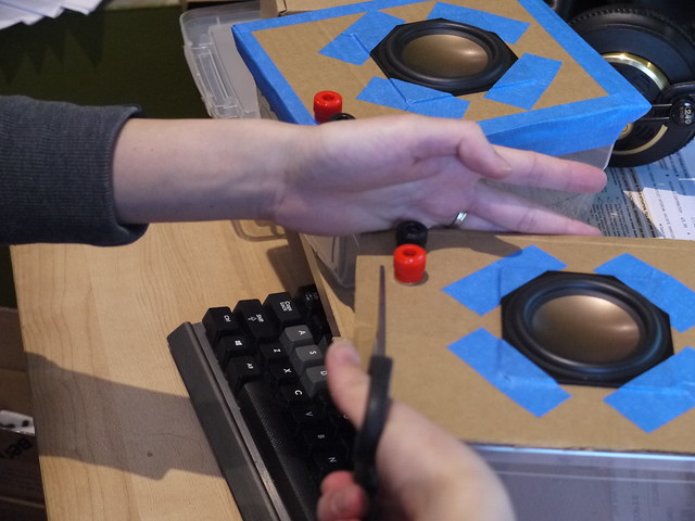
A fellow lab mate has been working on neat digital musical instrument design tools and making extensive use of a lasercutter for building prototypes. One thing I decided to try was using similar materials and techniques to quickly make speaker enclosures. I had a few HiVi B3S lying around, and have always wanted to make this design from zaph audio as a simple but good quality sounding kit. (confession: I totally skimped out on the crossover part). My attempt previously had worked, and while the little HiVi drivers gave out quite good sound, I can't help but the enclosures were holding the system back ;). So, armed with a relatively hassle way of quickly making very precise volume boxes together, I cobbled up a design using the handy makerbox.io tool and Inkscape. The former allows you generate finger joint designs of a specific dimension given a number of input parameters (the most important being the thickness of your material). Then I went into Inksscape and carved out the mounting holes and driver cutouts.

The project took two major iterations. First was making a perfectly sized box (according to zaph's design) with the driver and mounting cutouts, and then adjusting it due to issues encountered by the limitations of the materials used (i.e. very thin MDF).
P1050201
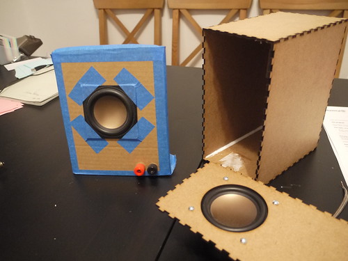
Old buildhack, showing the plastic box+cardboard baffle of the previous version and version 1 of the new design with single layer baffle


There were two main challenges I had with the new design, both relating to the baffle, or front surface where the driver is mounted:

1.) Because the 1/8" MDF is relatively thin, the baffle will actually bow forward a bit when the driver is mounted

2.) The finger joints are great at making an enclosed box, but once glued it is impossible to open it again without destroying the box. I didn't have the heart to simply glue everything together, and it's generally good to have your internal components accessible. Therefore, I had to come up with a removable baffle solution.

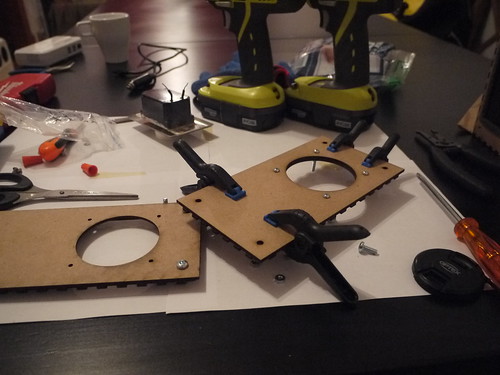
So, in the second iteration, I decided to double up on the front baffle (by simply gluing two pieces on top of each other), and then adding a non-removable component with a large hole like this:
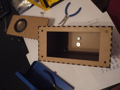
P1050246

Then, I put some t-nuts underneath the holes, and lined some insulation foam (weatherstripping) for better seal:
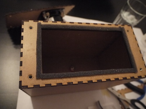

P1050251

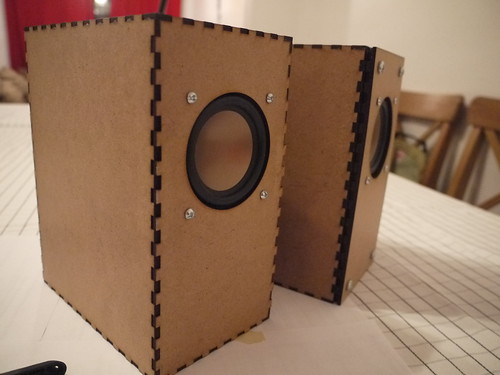
The t-nuts weren't ideal given the thickness of the panels, but with some glue and coaxing it worked. In the end, this design allowed the front baffle with the driver mounted to be screwed in. Here shows the version 1 (left) and version 2 (right) of the enclosure:
P1050259
Version 1 (left) shows a press-fit of the finger joint, and if I was building a one-off system simply gluing it would have worked but it would be a one-way trip!

The final version adds a bit of extra depth to the front, but allows the baffle to be removed for servicing. There is a slight gap since I recycled the old front baffle piece that had the finger joint edges. If I was to make a new version, I would simply cut out two non-jointed pieces (or even better: use thicker MDF if the cutter allows!). Below you can see the straight-cut piece with the old jointed piece glued underneath:
P1050257

All in all, it was a pretty fun project and good introduction to lasercutting. In terms of the sound while it is significantly improved over the plastic lunchbox design from before, I think it's still quite a bit aways from Zaph's original: no stuffing, box walls possibly too thin, weather stripping is most likely not as airtight as "speaker-grade" seals, and, perhaps most importantly - no crossover to block out the lower frequencies that the drivers would struggle to output anyway). However, powered by a lepai 2020a+ with signal fed by a small bluetooth adapter dongle, it makes a great kitchen/casual listening speaker with sound quality significantly better than off-the-shelf systems at much higher prices.

Here's a PDF of the lasercut outlines (for a real cut you may want to edit the line thickness to 0.1mm, change the colour etc to settings that your lasercutter requires). The design was done on 3 sheets of 30cm x 60cm 1/8" MDF that you can buy from Home Depot for a few bucks. (Thanks again Filipe for the materials+advice!) You'll need to make your own rear exit holes for the connector mounts of your choice: easiest is to just make two holes for banana plugs, which is what I did.

Could I have done this by hand? Sure. It would be a good practice of woodworking skills, and much easier to use thicker materials. However, there are certain things a lasercutter can do very well and for clumsy/lazy people like myself, this was a good excuse to play around and experiment.

Finally, a plug to Central Stamp for the accessible and quick turnaround laser cutting service!

Monday, February 23, 2015

What do you do when you get your 3D printer back online again? Use it to play music of course!
(and spend hours tweaking until a cube actually comes out as a cube...). A MIDI-gcode converter is responsible for converting MIDI notes into frequencies which are mapped to motor PWM signals. Kinda like the more impressive floppy drive organ

Overall I was surprised at how well it kept over time - I had some concerns over the wood warping. However, there were the typical calibration and bed leveling issues that make me wish I had invested in something with a metal chassis made of aluminum extrusions... Oh well, hope the Rhino 3d printer works out! 


Friday, January 30, 2015

Shutting down the RPi gracefully

One of the things thats worth considering when using an embedded linux system, is the integrity of the file system when it comes to pulling the plug. In the past, I've had issues (especially with poor quality SD cards) with file corruption. The RPi should not be simply disconnected from power when you're done, and if you're running an application without console access (either direct or via ssh), its a good idea to implement the means to shut down the system gracefully.

There is a large number of documentation on how this can be done via a physical switch connected to the GPIO pins. For my implementation, I aimed for the following:

- as few components as possible

- as straight forward header connections as possible

To achieve this, I ended up using pin 05 (GPIO03), which is conveniently located next to a GND (pin 6):


This pin has internal pull-up resistors enabled by default, which means you can use an active-low switch without having to add a resistor. To hook this up simply requires a 1x2 header connection attached to a switch (or bare wires, if you're into that sort of thing) on the other side.

Then, I employed the interrupt method (because polling constantly sucks, right? :P) as described here. The interrupt needs to be modified to trigger on the falling edge instead of rising, due to the active-low logic we're dealing with.

The unintentional bonus of using these two pins is that once the Pi is in the halted state, triggering this pin again will boot it up again! (This is likely a built-in feature which I luckily stumbled upon...)

The one weird thing I discovered, was that the interrupts do not fire when the script is running in the background, which might not be suitable for some usage scenarios since it requires load the python script last and keeping it in the foreground. I'm still investigating this...

Saturday, January 17, 2015

Raspberry Pi, openFrameworks, Analog to Digital stuff

Raspberry Pi, openFrameworks

I've been doing some work with the Raspberry Pi lately with openFrameworks, and it has served as a great reminder how accessible these hardware and software platforms are for building stuff.

Setting up the RPi for oF is super simple, and relatively well documented. The extra hurdle that is worth jumping over in the setup process, is cross compilation. I followed the official guide here, and found a few steps that were missing. The cool thing with oF is that its a very active community, and I was able to update the documentation, and push it to the official webpage within a matter of hours. Currently the instructions should be up to date for the active version (0.8.4).

Cross compiling on a desktop (i7-4770k) VM running Ubuntu sped up the compile time from over 1 hr for the entire library to less than 1 minute. Basic apps went from 2-3 minutes to a couple of seconds. Therefore, the amount of time it takes to set up the cross compile is more than worth it for any kind of significant dev work. Currently my setup involves SCP'ing the compiled binary to the RPi, but it would be possible to set up the shared file system to avoid this step. DistCC is also another way but is slightly more involved (IMO).

Media Performance

One of the applications I'm currently working on for the RPi, is the interactive playback of videos. Due to the well optimized GPU libraries available, the RPi has quite impressive video decoding capabilities for the amount of overall raw processing power. For oF, there is a nice wrapper of the OMXplayer on the Pi which takes full advantage of the hardware decoding capabilities. As such it is possible to easily run HD video in an interactive application in your openFrameworks app. Here's a nice page from creativecoding.net describing a few things you can do to get started with oF and Rpi

Analog to Digital on the RPi

One thing that the RPi lacks, compared to other boards like the BeagleBone Black, is built in analog to digital (A2D). The 26 GPIO pins (or 40 on the newer A+/B+ models) are digital only, so if you want to interface analog sensors, you have the following options:

- Use another microcontroller (such as the Arduino, teensy, etc) on the USB port and run an app that talks to the virtual serial-USB. This is quite common since the set up is very similar to when using such a microcontroller with a desktop/laptop environment. However, it does add a greater cost, and also on systems like the A/A+ board, you only have a single USB port that you might want to use for something else without having to add an extra hub...

- Interface an A2D on the GPIO. There are a few common methods, and each one requires some hardware that provides either: UART, I2C, SPI, or cook you own A2D solution such as described in this excellent post by Hertaville that also demonstrates how typical A2Ds work. For my initial attempt, I used the MCP3008 SPI chip, due to local retailer availability and some quick online reading. To get the pins of the RPi easily exposed on a breadboard, I used the ElecFreaks GPIO adapter kit. I'm not sure if I'm using it correctly, but there seems to be a major flaw in the design of this adapter board: the power rail pins do not line up with the rest of the header pins. Either I'm not using it the right way, or there was a bit of a design flaw here...


Anyway, here's a quick screenshot of a quick test program using using the wiringPi library:


Next steps: brushing up my PCB design to build a small breakout board for this chip, as well as looking at potential alternatives. The drawback of this SPI implementation is that without any further multiplexing, we're limited to one of two channels, which means a max of 16 input pins using 2 MCP3008's.

Sunday, January 04, 2015

DIY cheap-fancy speakers

Swan HiVi 3 inch "full range" speaker drivers (somewhat fancy), housed in the most budget enclosure. Consider using them in stand-alone digital musical instruments, although their weight was surprising. Also sounded quite anemic with a small 5W amp... may need something beefier, which drives up the power budget for portable applications. Right now we're testing these alongside the Pyle 4" cubes, which are amazing little boxes for their price. I suspect a better enclosure, and a low frequency cut-off will make these Swans sound even better...

P1040134