Monday, August 21, 2017

ESP32-based wireless BBQ probe

At work I've been using the ESP32 lately, and its proving to be a much more capable platform compared to the cheaper (but more mature) ESP8266. The great thing about the ESP32 is that it has a dual core processor, and a really adaptable I/O matrix that allows you to route hardware ports to many different pins. The flip side is that it costs a bit more (dev boards are around $10, while the chip itself is about $5. This makes the ESP8266 about half the price). Additionally, the software support is nowhere as developed and there are many bugs and undocumented stuff throughout, so for that the ESP8266 may be a more stable platform.

Over the past weekend, I played around with adapting a teensy-based thermocouple 

Part List

ESP32 dev board (this is the cheapest one with a lot of pins at $7USD currently. You can get a fancier one with built in OLED, or 18650 battery holder and charging circuitry for about $10. There's also one that has a standard Arduino Uno shape if thats what you're into...)
- Mobile phone power bank (I use a 5000mAh one that lasted comfortably overnight. a 10000mAh one like this one would probably power it for 2 days straight ;)
- Computer for programming, and monitoring temperature over http (via a browser)

Hardware Setup

The MAX6675 thermocouple driver uses a simple SPI connection. However, unlike many common setups, the chip doesn't take in any commands from the master so there is no MOSI line and only CS, MISO, and CLK are required. Once the chip select pin is pulled low, the resultant data gets sent out on the MISO line bit by bit for every CLK cycle. 

In this case, I used pins 18, 19, and 21 on the ESP32 for CLK, MOSI, and CS respectively.

The dev board has a micro-USB input for power (and programming), so to power it portably I simply use a power bank.

Software Setup

I'm using the Adafruit driver which can be found and downloaded automatically using the Arduino library manager. Note that like the ESP8266, you may need to add this change to explicitly implement the delay function as util/delay.h does not exist for the Arduino ESP32 library. The library allows you to hook up the MAX6675 to any pin that supports digital I/O, and using additional digital pins for the CS pin supports more than one probe driver if necessary.

To actually serve temperature values, I built upon the SimpleWifiServer example so that the user can access the value through the browser. As a lazy way to make the display update, I added a refresh tag to the served html so the browser will reload the page every 5 seconds. Hacky, but works!

The code is available here.

Test and Use

Here's a short test comparing it with a Thermopro wireless system: off by less than 2F at room temperature. Not bad!


I did a longer test while practicing the "snake" method which is a way to have a long and low temperature cooking technique for smoking on a Weber-style bowl BBQ. Here are some not-so-well-lit shots of the starting of the snake:


With a relatively short snake that spanned less than a third of the grill I managed to keep the temperature around 250~270F for about 3 hours. This bodes well as typical cooking times for pork ribs is around 3-5 hours (depend on a number of factors; here's a good recipe). And the snake could always be lengthened for really long cooks for brisket and larger roasts.

Next Steps

Here are some things I'd like to add to the system:

- a better web user interface!
- multiple probes: at least one for the grill and one for the food. almost essential to do any legitimate smoking.
- explore possibility of powering it directly off a thermoelectric module, making use of temperature difference between the BBQ enclosure and surrounding air.

*note: the MAX6675 is actually discontinued, but it is still widely available on most online retailers. Its replacement, the MAX31855, is also double the cost. What you get as extra are an extended temperature range, as well as some additional sensor info (e.g. probe short circuit detection, etc). Might play around with the newer chip at some point, but for now the 6675 will do... ;)

Monday, August 14, 2017

iPhone 7's slo-mo mode

The newer iPhones have this "slo-mo" mode, which is basically very fast video (240fps) that you can then tag a certain section to have it played back slowly.

On recent trips I managed to capture some interesting footage, for example: some seagulls that flock around the ferry in Helsinki harbour, on the way to Suomenlinna Island:


Or leaping dolphins at the National Aquarium in Baltimore: (note that we had been going here everyday for almost a week, which is why I got relatively good at anticipating when they do neat tricks. What I enjoyed about this aquarium is that they don't just make the dolphins do crowd-pleaser tricks, but take time to explain the kind of interactions and trainings they do to keep them healthy. Keeping marine mammals in captivity is a controversial subject...


Kinda cheesy, but pretty neat for the first while at least...

Sunday, July 23, 2017

Cheap 3" Drone for taking HD video

Ever since the intern Canadian UAV regulations were released, I've been wanting to put together a relatively cheap, but HD Camera carrying drone that is light enough to be exempt from any regulation. At the threshold of 250 grams, it was actually quite doable at a relatively low price given the extremely rapid developments in the DIY quadcopter industry over the past few years.

This is the second, but much more used iteration of the particular frame. The first had a 4 in 1 ESC and F4 controller which I blew up on a hard crash (did not disarm when it dove into the ground in acro mode), and due to parts I had available it was rebuilt using slightly less optimal (weight-wise) parts but ended up flying very well, so I kept it even after replacement parts arrived.

Before delving into the details, here's a google photos-created video from some footage I took while travelling in Finland for a conference. The small size of the quad means I can carry it easily in a backpack containing my work laptop (13" MBP) without adding too much extra weight.


Here's the finished build "in action" next to the transmitter, out on the field on Aalto University campus:


Parts list and build details

Frame: Realacc RX130 that came with a Matek PDB. (Used to be able to find it for about $13-15 on Aliexpress)

Motors: ReadyToSky 1306, 3100kV (available only on AliExpress from what I can find; example link. They are super cheap clones of the DYS 1306 at half the price, but the latter are much better in quality. Supposedly 4s capable but I've only ran them on 3s so far. Works fine!

ESCs: EMax 12A "BlHeli" which actually had to be manually programmed with "real" BlHeli. They're not super light but can be found for cheaper from eBay and AliExpress merchants. However, I would actually rebuild it with a BS412 (25x25mm) or maybe a RacerStar 4in1 (30.5x30.5mm). The latter is 20A and would work with 1407 motors which could support a larger craft (160mm frame swinging 4" props). A 4in1 (even larger 20A one) would also be considerably lighter than the 12A EMax's I'm using. For discrete ESCs the EMax Bullet series may be better as they're much smaller and lighter.

FC: I'm using a strange Piko BLX clone board that has a curious 23mm!? hole spacing. It fits in between the standoffs of the 30.5mm spaced stack, but is not ideal. I would probably just go with a full size 30.5mm FC for this frame next time... or else go 20x20.

Receiver: FlySky A8S. Tiny, supports failsafe fine despite product description stating otherwise, and no reliability issues that seem to be a problem with older versions that are no longer sold on BG...

Batteries: ZOP power 3s 500mAh 45C. They're not rated for consistency, and of the two I have one seem to work better than the other. Having said that both allow me to zoom around for about 3 minutes or so lugging the HD camera, or do more aggressive manoeuvres without the camera.

Props: DYS 3045. The only 3" props I've used so far. Seems to be a good match and they're pretty, so not too much to write about at this point... ;)

Camera: the trusty RunCam 2 HD. Weighing in at 50 grams with battery and SD card, its not the lightest option but its a nice action camera to boot. I could have shaved about 15 grams off by not using the battery and powering it off the 5V rail of the PDB instead. Another interesting option would be the new Split that weighs about 20 grams or so and has a faster analog signal for realtime FPV feed (requiring an analog transmitter of course), but the Split is pretty much a dedicated flight camera and can't be used elsewhere by itself.

Transmitter: The trusty FlySky i6 which I modded to 10ch, and the i6ab receiver is still working well on the 250 class quad.

The build weighs in at exactly 250 grams with the camera, which is about 15 grams more than when I had the BS412 4in1 ESC and F4 controller with built in 5V regulator which eliminated the need for a PDB. This means I don't have room for a lipo voltage checker/alarm (such as this one), and I have to go by gut feeling and go by experience from more open locations when I didn't need to conform to regulation.


Previously, with the lighter 4in1 ESC:


Here's some raw, unedited zooming-around-the-park footage:


All in all, a very fun quad that gets a lot more action than the 250 (5") one due to the size and legal status. The Canadian regulations have recently been updated to be a lot more reasonable, but anything that weighs over 250 grams (and less than 1kg) is still relatively restrictive in terms of space.

Tuesday, May 30, 2017

Sonifying Plant Moisture using a simple Algorithmic Arpeggiator

Putting together a number of projects related to the Raspberry pi, sensors, and node-red, this post describes the sonification of sensor values in a relatively simple but practical context.

After putting together the automated plant watering system and appending to a physical actuator to it, here we look at other ways of communicating the status of the system to the user: using sound and music!

Mapping sensor values to music

The concept of mapping sensor values to music in the context of new digital musical instruments is a deep and fascinating area of research (ok, I might be a bit biased here since this is the subject of my PhD work... :P). In a nutshell, the mapping problem can be laid out by the following components:

Input -> Mapping -> Synthesis

The input is the sensor signals that correspond to some physical phenomena of interest. Here we have a value that gives us a sense of the humidity levels (to be precise: it is difficult to get a sense of exactly how much water is in the soil, and I'm not even sure what would be the appropriate units to measure it... but what we do get is a relative number that moves up and down as the soil dries out, and that's what we're interested in here!) In our current situation, it is simply a single value coming from the moisture sensor, perhaps scaled to a more convenient range (lets say 0-100...)

The mapping is the part of the system where the sensors values are translated in a meaningful way into control parameters to drive the sound producing module. . While a rather abstract concept that is usually completely implemented virtually for most digital systems, this is an important part that ultimately defines how the system behaves (i.e. produces what kind of output, for a given input).

The synthesis component refers to the part that actually generates sound - typically attached to some kind of physical sound producing device. Here we build a small algorithmic arpeggiator that takes in parameters and generates notes that are being emitted in real time through a MIDI port which can be used to control any hardware synthesizer. (It probably makes sense to look into using a software synth on the Pi itself, for a more standalone solution in the future...)

Design of Mapping

The general behaviour was inspired by the system presented in the Music Room project. Here, two values (speed and proximity between two people) are used to drive an algorithmic composer that can respond in real time to generate music in a "classical" style. The sensor values here are mapped to concepts like valence and arousal, which in turn affect the tempo and key of the music being produced. (For more details check out the paper/video!). In our case we take a simplified but similar version of the concept.


Algorithmic Arpeggiator/Sequencer

The sequencer is implemented as a Python script, building on one of the examples in the mido library. It simply randomly selects from an array of notes and emits an note-on followed by a note-off message after a certain duration. I expose the relevant parameters via OSC to control the tempo (i.e. note duration), and the key (each scale name changes the contents of the note array). The Python code is available here and the OSC address/message handling is quite straight forward.  Of course, the possibilities for incorporating more complex and interesting musical concepts is endless, but we leave it here for now... :)

Software Architecture

Since most of our existing system is built in node-red, we simply add the necessary nodes to talk to the sequencer. The OSC node takes care of formatting the message, and then we simply pipe it out a UDP object to the correct local port where the Python script is listening.


node-red Configuration

Here's what the node-red configuration looks like. The top function node divides the moisture range into "pentatonic", "major",  and "minor" scales with decreasing moisture values. The tempo map function below provides an exponential scaling of the note durations, which cause a rather sharp change as you reach a "critically low" moisture value (to be fine-tuned).


The blue OSC nodes ("key" and "tempo") take care of the formatting of messages, and here they're sent to port 7002 on the same host where the Python sequencer is running. The entire flow is available here.

This is what the dashboard looks like, showing the changes in "key" and tempo (in Beats Per Minute) as the moisture decreases:


Audio/Video recording to come...

Soft Synths

It is possible to do all the sound generation on the RPi itself. I have experimented with amsynth running on the Pi, and after battling a bit with alsa configurations, managed to get the onboard soundcard to generate the actual audio as well. The universality of MIDI means you can have it any way you like!


Tuesday, May 02, 2017

Playing a MIDI keyboard in node-red

While likely not originally designed for typical IoT platforms, it is possible to play a MIDI keyboard in node-red via the GUI dashboard using a relatively simple setup.

For this somewhat unusual exercise, you will need:

- A Rasbperry Pi (can do this on a desktop platform, but whats the fun in that?)
- A USB-MIDI capable Keyboard. (You can use a USB-MIDI adapter with an older MIDI keyboard without USB of course)
- Install of the most recent node-red, with the dashboard. The only additional node you'll need is node-red-midi.

For further details check out the detailed writeup here.

Here's what it looks like in action. The computer monitor shows the flow as well as dashboard UI. Excuse my rats nest under the desk.


Some neat features:
- Works on any platform in the browser
- Allows concurrent connections, so more than one person can play with it at the same time on different devices 

Some obvious limits I can think of:
- limited UI from node-red-dashboard for this purpose; a row of buttons is not a great interface for an instrument
- multi-touch
- not tested for performance (latency, etc).

Next step: hooking up some music to the plant moisture sensor!

Tuesday, April 18, 2017

Raspberry Pi Plant Watering System

Here's what I've been working on at Infusion lately: documenting the Raspberry Pi based plant watering system that measures the moisture content of the soil and triggers a relay-driven valve to water the plant:


Control software was built using node-red, with a FRED endpoint to talk to the cloud-hosted node-red instance that allows a public dashboard to be displayed (public dashboard available here).


One of the awesome things about node-red is that you can easily view the dashboard from a browser, and with FRED you can access it anywhere:


Detailed hardware and software write-ups on the PiShield site.

Saturday, April 08, 2017

Cheapest Brushed Tricopter Ever? [Detailed Part 1]

[disclosure: some of the banggood links contain an affiliate code, but many products are discontinued or outdated so consider seeking current alternatives!] 

What started off as a mental exercise turned into an actual implementation of not the first, but perhaps cheapest possible brushed tricopter in existence that I'm aware of. An overview of the list of parts and some sample flights are available in this previous post.

Quick Intro

Before starting, there are some existing work including this one which basically describes the entire idea, but requires a very well made yet somewhat $$ Multiflite Pico flight controller. Since this was purely a casual exercise and I've already spent a hefty budget on larger brushless builds, I wanted to keep it as cheap as possible.

Main Challenges of a brushed Tricopter

The concept of a tricopter is relatively simple: instead of pairs matching counter-rotating in a quad (2 pairs laid out on the same plane), a Y-copter (2 side by side and 2 overlapping at the tail), hex (3 pairs, single plane), Y3 (3 pairs overlapping), Octo (4 pairs), etc... Instead, a tricopter has an odd number of rotors, which means that the yaw cannot be controlled via rotation of the driving propellers alone. In order for yaw compensation, a tail servo allows the third motor to tilt, providing the counter-rotating forces necessary to keep the craft pointing the same direction while having independent control of the overall throttle.

Both BetaFlight and CleanFlight have tricopter modes, and in these modes, the first two channels become servo controls while the remaining channels (3-6) become motor driving outputs. However, with brushless boards, normally only brushed motors are expected as outputs and so the PWM outputs are usually attached to the gate of a driving mosfet through a resistor, which then switches the motor pads between V+ and GND. This means that one would not be able to, out of the box, add any servo to these boards.

There are two main issues here:

First, I would need to bypass the MOSFET motor output of the servo channel for the tail. This would involve finding a spot on the PCB to solder an extra wire to.

Second, I would need to move the motors to channels 3, 4, 5. Here's where another issues arises: most brushed FC's that physically support only 4 motors are hardwired to channels 1-4, which means there are only mosfet drivers and motor pin pads for those channels. The reassignment in tricopter configuration would result in channels 3, 4, 5 being used, and channel 5 would not have any driving circuitry. While it would be possible to hack the FC code (BF or CF) to move the servo assignment to, say, ch 5 or 6 and retain the motor driving hardware, there is a further issue since on the PCBs, the latter channels are completely unused (not soldered to anything), and would require direct soldering of a fine wire to the tiny pins on the QFP microcontroller package itself- not a feat for the faint of heart!

*edit*: a helpful redditor mentioned that in BetaFlight the resource mapping function could potentially solve some of these issues without recompiling the FC code. It doesn't quite solve the problem of potentially having to solder directly onto the microcontroller package, but its a start! May be worth trying out as there are a number of cheap F3 brushed controllers out there that only have 4 motor drivers...

The Multiflite Pico is the only brushed FC I'm aware of that explicitly exposes servo output on a pad, which makes building a tri possible. However, it is also out of budget for this project. (And if you've ever flown a brushless mini-quad of *any* size, you probably don't want to invest any significant amount of cash into any brushed build these days... but I digress.)

The Solution

As luck would have it, the Eachine Naze32 brushed board (many clones under "HappyModel" and "Realacc" exist from various other retailers, and in fact the "Eachine" branded one actually came with Realacc markings on the bottom... ;) is a hex-capable brushed flight controller that I also had an extra of on hand from the popsicle quad build. This means that there are additional mosfet channels available, so even after the servo assignment to CH1 and 2, it would still be possible to use motor channels 3-5. The next step is to find exactly where the CH1 motor output is. For that, I dug up the naze32 schematic along with the datasheet of the STM32F microcontroller. Following (red rectangles in the image below) show the pin we're interested in:


What you see on the actual board is one pin of a SMD resistor that connects between the microcontroller's PA8 pin (29 on package), and the gate of the MOSFET for motor 1. After checking with a multimeter and confirming those two are indeed the same point, I proceeded to solder a wire onto that pad which should in theory provide the PWM servo output. (It might not look that difference in size, but its MUCH easier to solder onto that SMD pad than the leg of the microcontroller itself - not only is it considerably larger, but perhaps more importantly, there are no other pins nearby!). It was also a good time to test out the fine tip of my new super cheap (but working well so far) iron. Here's what it looks like:


The white cable is the signal, while brown (5V) and black (GND) make up the rest of the servo connections. Since the micro-servos I plan on using is super low power, using the 5V regulator of the board is OK. However, looking back it would have probably been better to use VBatt directly (unless I plan to use this board in 2-cell mode with more powerful motors... more on that later). Since the white cable is just connected to the resistor pad, adding a dab of super glue under the white cable prevents it from ripping off.

Next up is to test that it works:


And it does!!!

Second part of the build log TBA...

Tuesday, March 28, 2017

Cheapest Brushed Tricopter Ever? [overview]

Here's adding to the family of brushed, popsicle-frame based micro-copters: a tricopter!

The first part of a detailed build is available here. This post is mostly an overview of the parts used as well as some sample flights.


Part list:

- Eachine Naze32 Brushed FC ($7): note that newer ones like the F3 will not work. (Or at least not as easy)
- DasMikro FlySky Receiver ($10): version B, for PPM output on CH8.
- Eachine 8520 Motors ($12): I'm really interested to try the RacerStar or Chao-Li ones to see if I can get a bit more oomph out of them, as currently its a bit anemic even with ladybird props. Maybe 2s?? :P
- Ladybird 55mm props ($8): works great now for the quadcopter. Have some 65mm King Kongs on way which hopefully provides more power and are considerably cheaper at $5 for 10 pairs intead of $8. There are less clearance issues on the tri compared to the quad.
- 3.7g servo ($2.50): could have gone lighter, but was the cheapest I could find on AliExpress at $2.50. The Emax 2.5g should work too (and may be better quality) but is a whopping $5!
- 1x rubber grommet ($1.50) for ghetto-mounting the tail motor to servo horn
- 3x "craft grade" popsicle sticks from the dollar store
- Prop guards ($2.30)
- Elastic bands

AUW is about 50 grams before camera.

Total was a bit over $40 without FPV stuff, with a lot of spare props and grommets, plus an extra motor (Since the tail servo handles all the yaw and the number of motors are odd anyway, the third motor can be any direction). Not super cheap compared to RTF quads available on the market these days, but I'm not aware of a tri in this price range, and it was a pretty fun build process! I would love to hear how one might go cheaper on this if anyone has any ideas! :) I expect 720 motors could work, but the cost savings would be negligible. Oh and I forgot to include the price of the battery, which was from my V222 quad...

Using FlySky i6 receiver with 10-ch mod. (swich off AFHDS 2A to bind).

Indoor flight:


Outdoor flight:


While not as anemic as the initial popsicle quad with the weak triblades, its definitely could do with some more power. Hopefully the 65mm props in the mail would help. I should also consider removing the prop guards as they add a tiny bit of weight, and also see if getting different batteries would help. (These are from a unbranded multi-pack I got for my V222, and there's no discharge rating on them. Have some 600mAh 25C's coming, so will see if the battery may be the limiting factor here...)

*update* the 65mm props have arrived, and there's a lot more thrust now! Check it out:


And some flight footage:


*update2*: Yet another outdoor video with the 65mm props:


This time I had a larger area to play in and was able to fly a bit harder. It flew well generally, but I'm finding that the props are a bit loose and pop out relatively easily (this could have been after an incident where I crashed it indoors while tuning perhaps)... by the end of the second pack, I had lost the tail prop in flight and crashed it such that one of the main popsicle sticks have unglued... luckily all electronics appear to be intact. back to the workbench!


Bonus pic the happy DIY multicoper family (so far):


Thursday, March 02, 2017

Popsicle Quad, V2

So after the first version, made with HaagenDaz sticks flew a bit, I wanted to make some upgrades. Specifically, I wanted a.)more power and b.) a bit more clearance to mount an AIO FPV (all-in-one first-person-view) camera, such as the TX02 that I had on hand. To do so, alas, would require a slightly larger frame. So I picked up a bunch of "craft grade" popsicle sticks (there's only so much sugar we can handle) from the dollar store, and got to designing a new frame.

I wanted to keep on using the rubber grommets as before, which were quite good at holding the motors. The final design I came up with the following: (series of relatively self-explanatory photos)


The end result, with the old Eachine triblades:


The new props, based on the suggestion of a redditor, are the 55mm ladybird props. I also tried some hubsan x4 props which were also an improvement, but only had a set and broke them quickly testing indoors ;) I see some newer KingKong 55mm and 65mm props, which might also be good to try out. They are also a bit cheaper at $5usd for 10 pairs instead of ~$8 for 8!! The main thing is to use props with 1mm shaft holes, and to ensure there's enough clearance of course!


Looks like the props are about half a gram heavier each. The extra thrust however, was totally worth it. It's actually a bit hard to fly indoors without a prop guard, so I waited a while before good weather and opportunity arose. Here's a flight in a park taken with a run cam 2 (sorry for slanted camera placement... it's a bit hard to tell sometimes ;)


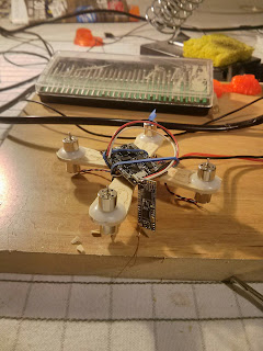
Unfortunately, I haven't had time to do any FPV flights with it, and my ghetto FPV system (to be described at some point) is quite clunky. The camera adds 10 lbs 5 grams, which is about 10% the total weight of the quad. Being 200mW it also draws about 400mW, which is not negligible for such small flight batteries. A 25mW (such as the TX01 or the switchable power TX03) transmitter would be more appropriate for this build.

Saturday, February 25, 2017

HäagenQuad Micro: a tiny quadcopter based on an ice cream stick frame

Since the weather is pretty unforgiving here in the wintertime, I wanted to build a small indoor micro-sized quadcopter but still keep the control systems that are present in the larger racing/acro machines.

Originally wanting to use a 3D printed frame for this build, but after having calibration and belt wear on the Y axis, I ended up with something a bit different while the replacement parts for the printer are yet to be installed. This attempt to use popsicle sticks for a quad frame is by no means the first, but unlike that example I'm using separate "DIY" quadcopter components (typically found on Eachine QX-series for those who want to just get a complete kit with all the parts). The advantage is you get a fully configurable flight controller that can run Beta/FleanFlight, but the tradeoff is you need an actual transmitter which increases the cost. I'm using the FlySky i6.


Everything is available from Banggood. For Canada I've found that using the registered + insured option gets the shipment faster, and may help alleviate issues as experienced by many. (For other Chinese retailers, the ePacket option is great as well)


Here's a complete list of parts along with their product links. (Prices may fluctuate due to sales etc). Note they are affiliate links which mean while its the same price as if you went on the site normally, purchases generate a very small commission for me. First time trying this feature out...

Motors/props ($11.25 USD): Eachine 820 Motor (4x) + Props kit (2 sets)

I'm guessing they're similar to the ChaoLi motors. They come in CW (red+ blue-) and CCW (white+ black+) wiring. While they might spin when polarity is reversed, from what I understand the brushes may wear out much more quickly so its best to make sure they're hooked up correctly!

If I was to order again, I might try the RacerStar ones, which may be better (or simply better looking with the nice red paint scheme... red means faster, right?? ;))

Flight Controller  ($7.05 USD): Eachine Naze32 Brushed Controller

In the racing multicopter community the Naze32 is starting to show its age, and F3/F4/F?? controllers with faster processors are starting to become the standard. While the latter are available for brushed builds, it's not really necessary for a small project like this. However, I've noticed that at least F3 based ones are only a few bucks more, so if I was to make another one, I'd probably go with those. One other option would be to go with a built in receiver, such as this one for FlySky, which would make the wiring and mounting a lot cleaner! The tradeoff of course is you won't be able to use the receiver by itself for another project... Similar options exist for DSM and FrSky

Receiver ($10 USD): DasMikro Ultra Mini

Select "Type B", which has the PPM out and makes wiring super easy. Also supports 8CH with a modded Flysky i6, so you can add extra switches and knobs if you like to additional AUX channels!


Rubber Grommets for motor mounting ($1.60 USD): 20 pack 

Make sure you select the 8mm version. Outer diameter is about 10mm, not counting the lips that stick out a bit further. 10mm an important dimension as that should be the size of the hole on the arms.

JST/losi Connectors:

Instead of the losi battery connector that came with the FC, I went with the 2.54 JST since I had a bunch of those lying around.

Others:

- 2x Häagen-Dazs ice cream sticks (other popsicle sticks may work, if the ends are wider than 10mm)

- Elastic Bands

- Bits of paper etc to stick under the FC to make it level with the frame, if needed

Build Process

The trickiest part of the build, for someone not familiar with woodworking is getting the right sized hole on the arms. At first I was ambitious and wanted to drill an enclosed hole, but quickly found out that it is very difficult to do so with a regular power drill. It turns out for delicate wood like this the best way to cut through is either with a small knife, or a really high RPM grinding tool (e.g. Dremel, etc) with the right attachment. Also in the end I found out that it's OK for the outside to be open as the grommet will still sit snugly in the opening, as follows:


The first thing I wired up was the FC to the radio. Since we're using PPM, we only need a single signal wire, as follows:


Then, we just have to connect up the motors to each channel. I soldered directly onto the FC, and the only thing you have to make sure is the right motor direction. For CleanFlight, the directions are:


So motors 1 and 4 are CW, while 2 and 3 are CCW. The Red+/Blue- wired motors are CW, while the White+/Black- are CCW, respectively. So we just have to solder each motor to the correct pins on the FC:


I skipped a few photos along the way, but here's what it looks like all hooked up:


The battery get strapped in underneath, using the same elastic that holds the FC in place. Not the most secure mount, but it works!

Here's the AUW of everything:


At almost 50 grams, it is interesting to see that there are many brushless builds these days that are around similar weight. Exciting times we live in! Anyway... how does it fly?


Turns out, not very well! After some discussion online, people have recommended me to move away from the triblade props that come with the eachine motors. While they are super quiet, there isn't a lot of power. I have some ladybird props on the way which should make a difference. Stay tuned!

Here's an updated outdoor video using the new ladybirds. As you can see it actually manages to get off the ground (and clips a tree at one point and still recovers...)


Other Potential Changes

I haven't decided if I should switch everything to losi since they're much easier to plug/unplug compared to JST. On the other hand I have 5 batteries with JST already and it would take quite a bit of soldering to change them...

Finally, a family pic with a WlToys V222 (showing its age compared to modern toy quad options, but still a great intro to quadcopters), and the perpetually in-progress QAV250:


Bonus Peek:

Here's the next version, with larger and more powerful props (hubsan x4 shown, but also have ladyprops which feel even better), as well as an AIO video tx:


Tuesday, January 24, 2017

Harmochord restoration with a 3D printer (mostly Dad's work!)

In the summer of 2016, we stumbled across an interesting find at a pawn shop in Verdun:


It's basically an accordion with an electric pump instead of the manual bellows, designed as a table-top instrument! Single bank of reeds for the keyboard, and a relatively small array of bass notes compared to the full size accordions

After trying it out in the store and verifying that at least every key makes a sound, we decided it was worth the $20 and the effort to lug it back home on the bus (it probably weighs around $15kg or so...)

The things that were apparent immediately:

- It was "Made in West Germany", which makes it probably the most interesting instrument I have owned thus far...
- pump appears to work fine
- 3 black keys are missing
- a few of the bass notes would stick when pressed

Things we found out afterwards:

- The "briefcase" actually was supposed to contain 3 legs, which allows the instrument to be self standing. Those were missing as well. (oh well...)
- slight leakage in some of the bass notes, causing either weaker sounds or other tones when some notes were pressed

As a keyboard player, the first thing I wanted to do was to get replacements for the black keys. Never got around to it with busy school and family schedule, but when my dad stayed with us for a bit, he took on the project.

This is mostly a documentation of the result of his efforts!

Here's a close-up of the missing keys:


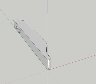
A 3D printed model was made in SketchUp:


It was a basic 2D profile that was pulled upwards, and then a small rectangular extrusion was added (top left of picture).

Here's the key being printed and the finished product:


Here are keys in their final location. Note that the key bed (not 100% sure if that's the right term here) isn't in the best of shape, so things aren't super aligned and some of the existing keys also aren't completely straight either.


Finally, a short demo of how it sounds:


There are a few more things that need to be fixed. My dad managed to get rid of the sticky behaviour of the bass notes, but the leakiness of some of the notes are still there. Here are some shots of the mechanism when it was open, for curiosity's sake:


So at some point, I might tackle that... (but there's also a good chance it won't happen until the next time Dad visits! ;)